
Home/Projects/Orlando Fire Station 6

Case study — Municipal / essential facility

142 kW on a fire station that could not go offline.

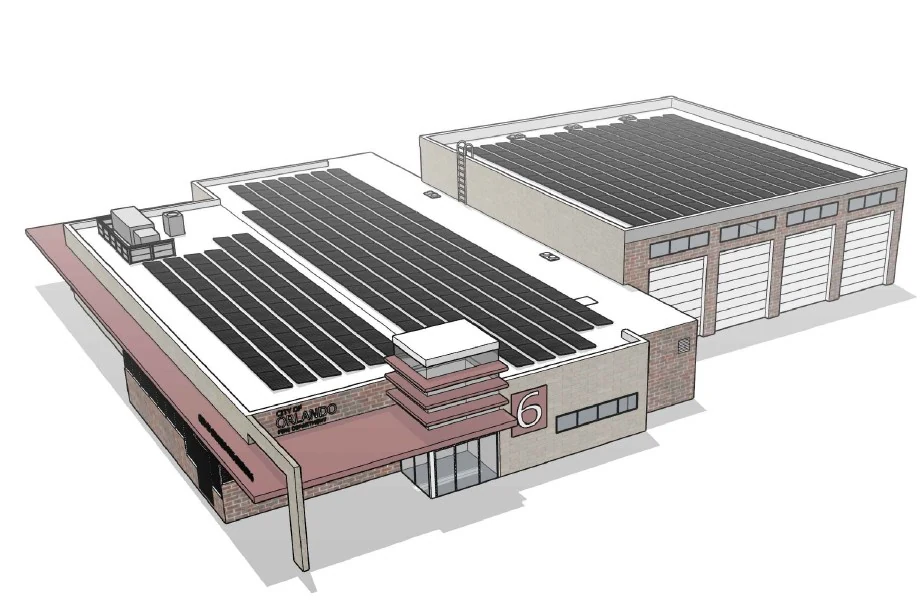
Orlando Fire Station 6, 3900 E Concord Street. A rooftop grid-tie array designed to Risk Category IV over an active apparatus bay, sealed for the City of Orlando in August 2021.

Design model showing the solar array across the main station roof and apparatus bay at Orlando Fire Station 6
Design model — array split across the main station roof and the apparatus bay.
System data
DC system size142.27 kW
AC system size112.9 kW
DC/AC ratio1.26
Modules347 × 410 W, 72 half-cut cells
Inverters2 × SolarEdge SE43.2K, 1 × SE17.3K, 1 × SE9K
Optimizers164 × P860, 22 × P505
RackingGridFlex, ballasted
Roof typeTPO membrane
Design wind speed140 mph, Exposure C
Risk categoryIV — essential facility
Service800 A, 120/208 V, 3-phase 4-wire
AHJCity of Orlando
SealedAugust 2021
RoleDesign engineer & engineer of record

01 / Constraints

Three things made this set harder than its size suggests.

01

Risk Category IV

A fire station has to stay standing and operating through the design storm. That pushes the importance factor to the top of the table, so every attachment, ballast block and uplift check is run against a heavier load than the same array on a house next door.
02

140 mph over TPO

A single-ply membrane roof will not take arbitrary penetrations, and Exposure C at 140 mph is unforgiving at roof edges and corners. The layout keeps modules inside the field zones and off the high-uplift perimeter.

03

Fire-rated penetrations

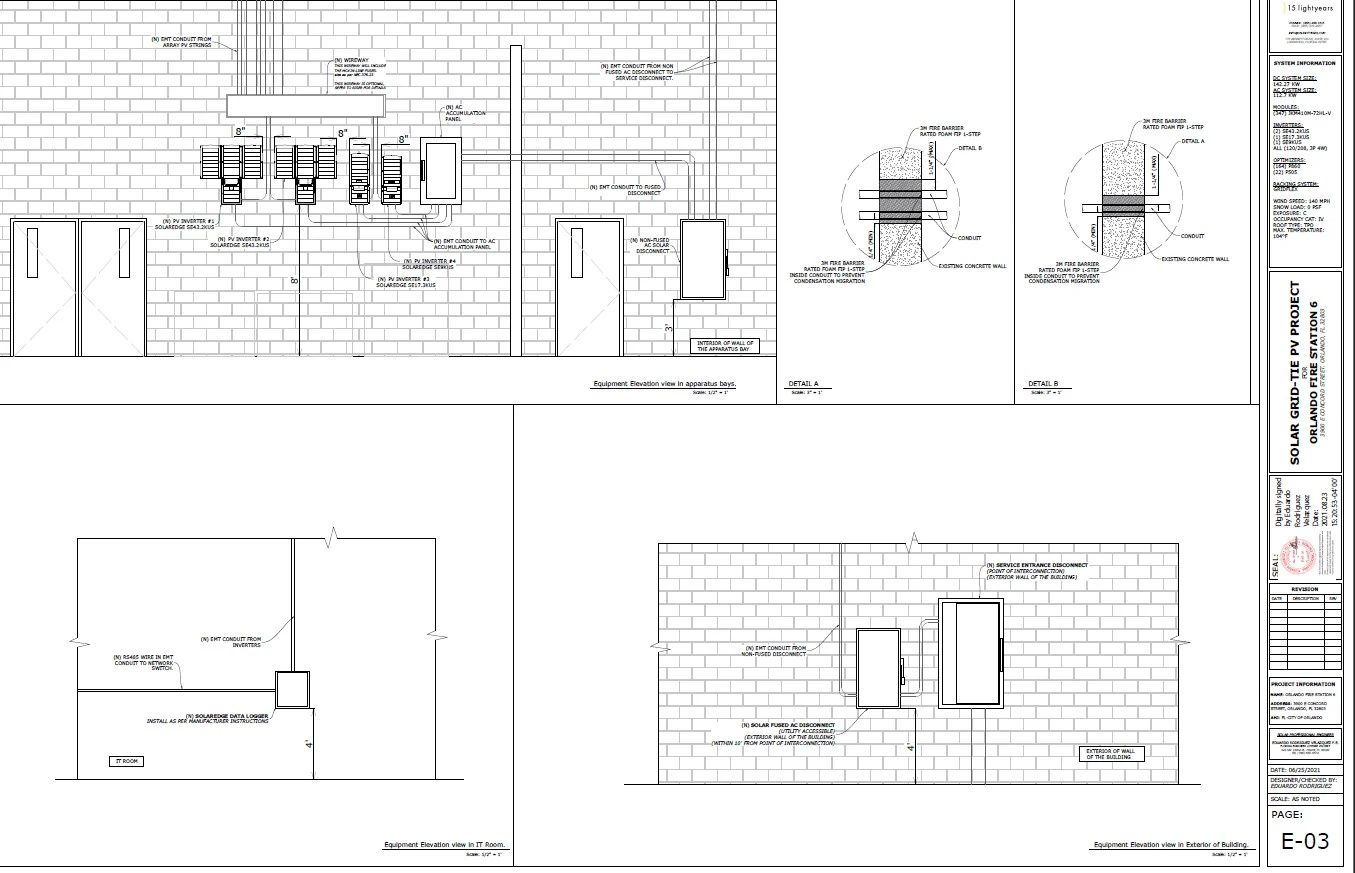
Conduit runs cross rated concrete walls into the apparatus bay. Each crossing is drawn as a detail with a rated fire-barrier foam step and a condensation break, so the inspector is not left interpreting a note.

02 / Sheets

What the reviewer received.

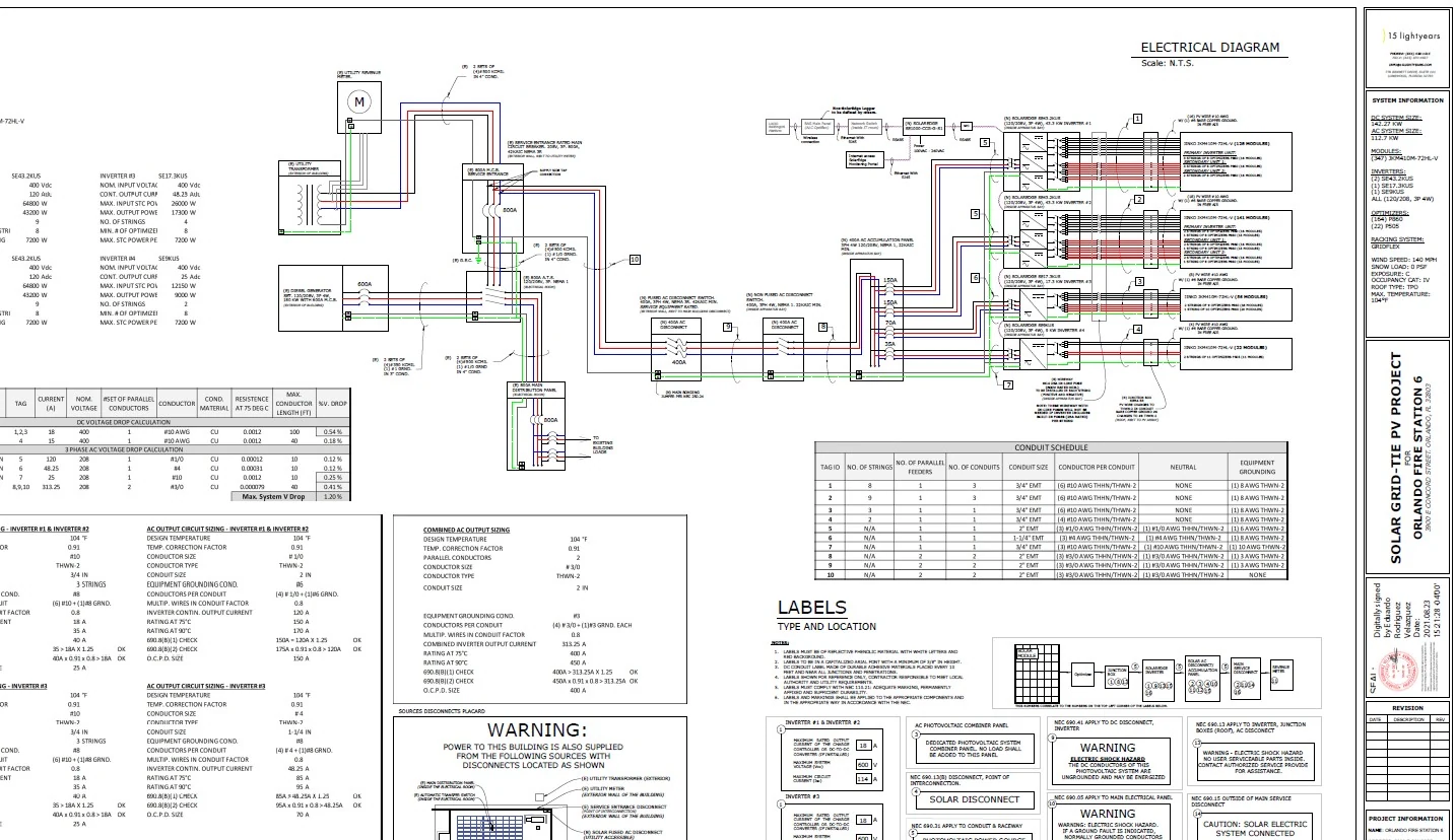
Full electrical one-line diagram for Orlando Fire Station 6 with conduit schedule and calculations
Electrical diagram. Every string traced from module to the 800 A service entrance: four inverter groups, an AC accumulation panel, fused and non-fused disconnects, and the utility transformer. The sheet carries its own conduit schedule, DC and three-phase AC voltage-drop tables — total system drop 1.20% — OCPD sizing checked against NEC 690.8(B), and a drawn placard schedule showing each label’s type and location.
Sheet E-03 showing equipment elevations and fire barrier penetration details
Sheet E-03 — equipment elevations. Inverters and the AC accumulation panel dimensioned on the apparatus bay wall, the SolarEdge data logger in the IT room, and the service entrance disconnect on the building exterior within 10 ft of the point of interconnection. Details A and B resolve the rated wall crossings.

03 / Outcome

Sealed, permitted, built.

The set was sealed in August 2021 and permitted by the City of Orlando.

A municipal reviewer should never have to phone the engineer to understand a drawing. If the detail is on the sheet, the review moves.

The same approach scales down. A residential retrofit gets the same discipline — calculations shown, labels drawn, details resolved — on a shorter sheet index.

Back to all projects

Have a commercial or municipal roof in play?

Send the address, roof type and utility. I’ll tell you what the set needs before you quote it.