Home/Projects

Selected work

Municipal roofs, residential retrofits, and the sheets behind them.

More than 4,000 permitted projects have gone out of this office. Below is a cross-section — built systems, design models and the sealed drawing sheets that got them through review.

01 / Case study

Orlando Fire Station 6

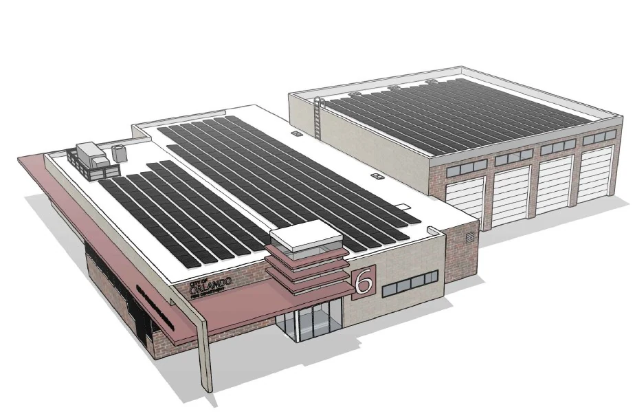
Design model of the 142 kW rooftop array at Orlando Fire Station 6
Design model — main station and apparatus bay roofs.

A 142 kW rooftop array on an operating fire station. Because a fire station is an essential facility, the whole set is designed to Risk Category IV — the strictest loading class in the code — at 140 mph design wind over a TPO membrane roof.

Four SolarEdge inverters feed an AC accumulation panel, with fire-rated penetration details drawn for every conduit that crosses the apparatus bay wall, and a data logger tied back to the station IT room.

142.27 kW DC 112.9 kW AC 347 modules Risk Cat. IV City of Orlando

Read the full case study

02 / Built work

Systems on Florida roofs.

Every array below was permitted from a set drawn and sealed in this office.

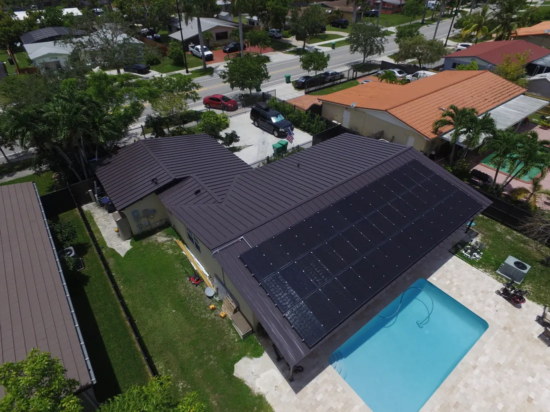
All-black solar array on a standing-seam metal roof beside a pool in Miami-Dade Residential

Standing-seam metal roof array

A full-slope, all-black array covering the entire south face of a Miami-Dade residence. Clamped directly to the standing seams, so the roof was never penetrated and the manufacturer warranty stayed intact.

Miami-DadeStanding seamRail-less clamps
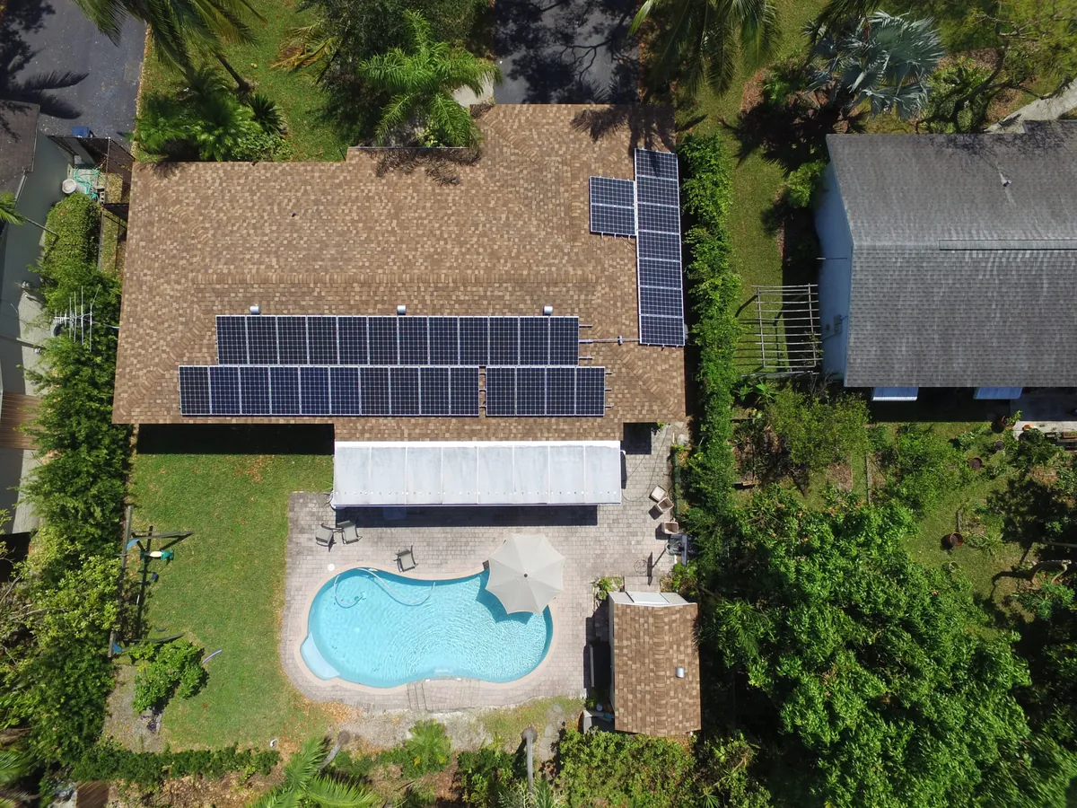
Two-orientation solar array on a shingle roof surrounded by mature tree cover Residential

Two-orientation shingle roof array

A composition-shingle roof split across two orientations and boxed in by mature tree cover. The layout was driven by the shade study — modules only where they actually produce.

South FloridaShingleShade-driven layout

03 / Drawings

The part your reviewer actually reads.

Photographs sell the finished job. These sheets are what decides whether the permit clears on the first pass.

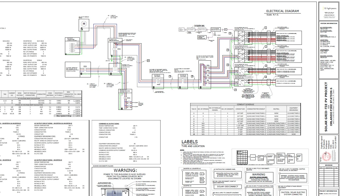
Electrical one-line diagram with conduit schedule, voltage drop calculations and label details
Electrical diagram — Orlando Fire Station 6. Full one-line from modules to the 800 A service, with conduit schedule, DC and three-phase AC voltage-drop calculations, OCPD sizing checks against NEC 690.8(B), and every required label drawn with its type and location.
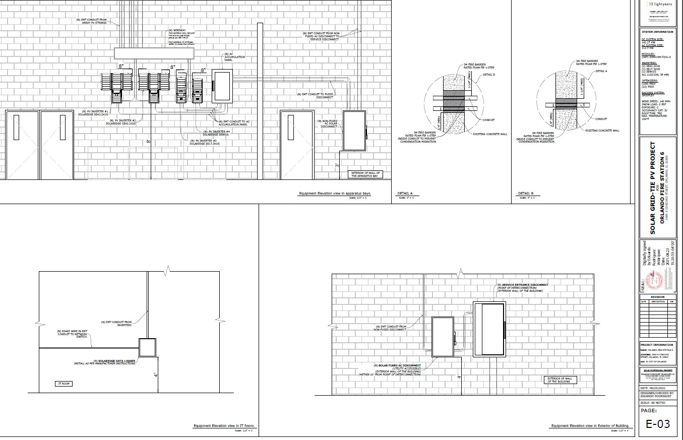
Equipment elevation sheet showing inverter layout and fire barrier penetration details
Equipment elevations — sheet E-03. Inverter and disconnect elevations inside the apparatus bay, IT room data logger, exterior service entrance, plus two detail callouts for fire-rated conduit penetrations through the existing concrete wall.
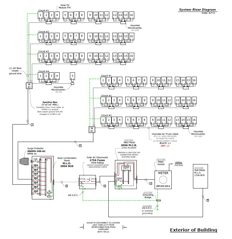
Residential system riser diagram with microinverter circuits and a 200 amp combiner panel
Residential riser diagram. Seven microinverter circuits into a 200 A combination panel with surge protection, a 175 A fused AC disconnect, and a line-side tap detailed at the existing 200 A service.
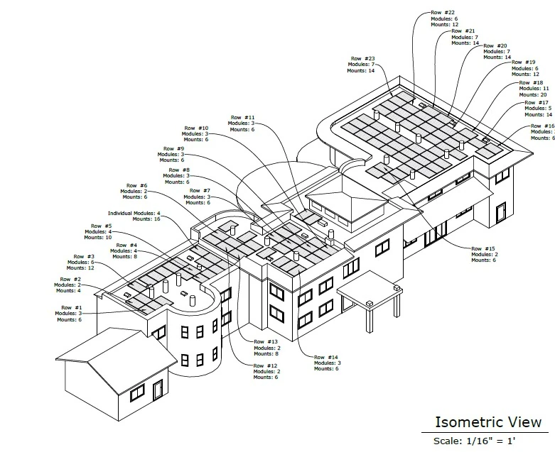
Isometric drawing of an estate with twenty-three module rows individually tagged
Estate isometric. Twenty-three separate module rows across a multi-level roof, each tagged with its module and mount count so the crew can stage hardware row by row instead of guessing.
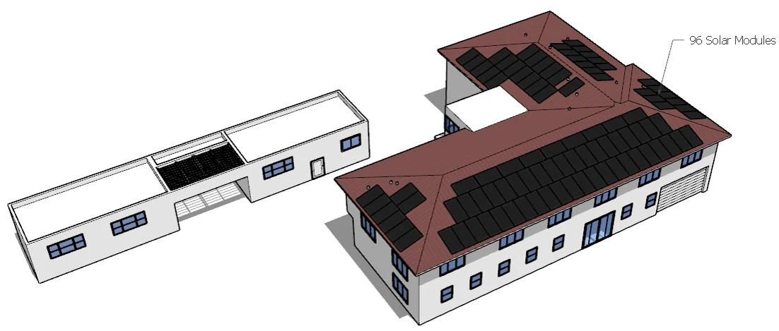
Design model of a 96-module array across two commercial buildings
Commercial design model. A 96-module array laid across a hip roof and an adjacent outbuilding, modelled before layout to confirm setbacks and walkways.
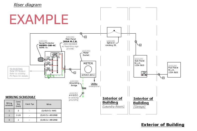
Annotated sample riser diagram with a wiring schedule
Annotated sample. The reference riser I share with contractors so everyone agrees on conductor sizes and interconnection method before the set is drawn.

04 / Deliverable

What arrives in your inbox.

A single sealed PDF, sheet-numbered and ready to upload to the AHJ portal.

Sheet count varies with scope — a simple residential retrofit runs lighter than an essential-facility commercial array — but the structure is consistent, so your permit runner always knows where to look.

See the full service list

Typical sheet index
PV-1Cover, code summary, project data
PV-2Site plan and fire setbacks
PV-3Roof plan, module layout, attachment schedule
S-1Structural details, uplift, mounting
E-1Single-line and riser diagram
E-2Calculations: string sizing, OCPD, voltage drop
E-3Equipment elevations and details
E-4Placards and labelling
SpecManufacturer datasheets and listings
Working on a project that needs a reference? Much of my work is covered by client confidentiality, so not every job can be published here. Get in touch and I’ll share relevant sealed examples and contractor references for a scope like yours.

Want a set like these for your job?

Send the address, scope and equipment list. Fixed price and a date, same day.